How to Work with Fast-Failover OpenFlow Groups
- Ryan Izard
- Geddings Barrineau
Table of Contents
Prerequisites and Requirements
This is an advanced tutorial for OpenFlow 1.1+ groups. Please acquaint yourself with Floodlight prior to attempting this tutorial. Recommended prerequisites are:
- How to Write a Floodlight Module
- How to Use OpenFlowJ-Loxigen (the OpenFlow API exposed in Floodlight)
- How to Write a REST Application
It is also assumed you have a working knowledge of networking, SDN concepts (e.g. separate control and data planes), and know your way around the Linux terminal.
This tutorial comes with instructions geared towards the GENI testbed and for mininet. For those who have access to GENI (it's free if you do), you may use the rspec provided, setup your resources, and run the tutorial according to the provided instructions. For those who do not have access to GENI, no need to fret, this tutorial can also be done in mininet with the custom topology provided or with your own setup using the same topology.
Open vSwitch (OVS) version 2.3.1 or higher is required to use FAST-FAILOVER OpenFlow groups. The GENI rspec specifies an image that satisfies this requirement already, but if you are using mininet, please be sure to use OVS 2.3.1 or higher or another compatible virtual switch.
This tutorial uses a topology with a loop. Forwarding/LearningSwitch has been disabled in the version of Floodlight provided. If you wish to implement everything yourself with your own Floodlight controller, please be careful to eliminate the risk of broadcast storms.
Introduction
Ever wondered what OpenFlow 1.3 (well, actually OpenFlow 1.1 and up) groups are? Want to know how you can use groups for your research, experiments, products, and so forth? If you answered "yes" to any of these questions, then you're in the right place.
OpenFlow groups were introduced in OpenFlow 1.1 as a way to perform more complex operations on packets that cannot be defined within a flow alone. There are different types of groups defined in the OpenFlow specification to serve a variety of purposes. In this tutorial, we will learn how OpenFlow groups can be used to solve a real-world problem. Specifically, we will use OpenFlow groups to demonstrate how to quickly react and adapt to port or link failures.
Background
Redundant links are frequently used in network topology design in order to reduce the risk of end-to-end connectivity failure due to a single link or port down event on a forwarding device such as an Ethernet switch (e.g. due to an accidental fiber cut or network maintenance). In traditional, non-software defined networks, persistent traffic mirroring and custom configuration of individual forwarding devices can be used to achieve link redundancy. In an OpenFlow 1.0 SDN, the global network knowledge of the control plane allows a new path to be chosen on the fly to circumnavigate the failed link. However, communication between the data and the control planes is required in order to detect, compute, and insert rules that realize the new path. This adds latency between when the failure occurs and when the new route is established – latency that can adversely impact time-sensitive applications utilizing the network (e.g. live video conferencing). It also results in all packets being lost from the time of failure until the new route is pushed to the data plane.
As such, there is a need in the data plane for the support of fast-failovers to alternative links without control plane consultation and with minimal packet loss. OpenFlow 1.3’s group tables can be used for this purpose; specifically, the FAST-FAILOVER group type can be very useful to accomplish what we desire. Note that OpenFlow 1.1 introduced group tables and is capable of performing the same task; however, we will focus on and refer to groups in an OpenFlow 1.3 context due to OpenFlow 1.3’s more widespread adoption.
OpenFlow Groups
Before we can discuss how the fast-failover group works, we need to first discuss what an OpenFlow group is in general, and also give an overview of the various group types.
An OpenFlow group is an abstraction that facilitates more complex and specialized packet operations that cannot easily be performed through a flow table entry. Each group receives packets as input and performs any OpenFlow actions on these packets. A group is not capable of performing any OpenFlow instructions, so it cannot send packets to other flow tables or meters. Furthermore, it is expected that packets have been matched appropriately prior to entry to a group, as groups do not support matching on packets – groups are merely mechanisms to perform advanced actions or sets of actions.
As shown in Figure 1, the power of a group is that it contains separate lists of actions, and each individual action list is referred to as an OpenFlow bucket. Thus, it is said that a group contains a bucket list (or a list of lists of actions). Each bucket or list of buckets can be applied to entering packets; the exact behavior depends on the group type. There certain types of groups that make use of additional parameters within a bucket. The details of these parameters will be discussed with each group type, where applicable.
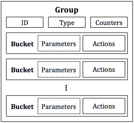
Figure 1: Components of a group and a bucket. A bucket’s parameters are only defined for certain group types. A bucket’s actions consist of any set of OpenFlow actions.
There are four types of groups – ALL, SELECT, INDIRECT, and FAST-FAILOVER.
The ALL Group
Starting with one of the simplest, the ALL group, illustrated in Figure 2, will take any packet received as input and duplicate it to be operated on independently by each bucket in the bucket list. In this way, an ALL group can be used to replicate and then operate on separate copies of the packet defined by the actions in each bucket. Different and distinct actions can be in each bucket, which allows different operations to be performed on different copies of the packet.
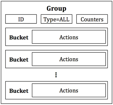
Figure 2: The ALL group. Every bucket receives a copy of any packet that enters the group. Buckets consist of actions and do not contain special parameters.
The SELECT Group
Next, there is the SELECT group, which is primarily designed for load balancing. As indicated in Figure 3, each bucket in a SELECT group has an assigned weight, and each packet that enters the group is sent to a single bucket. The bucket selection algorithm is undefined and is dependent on the switch’s implementation; however, weighted round robin is perhaps the most obvious and simplest choice of packet distribution to buckets. The weight of a bucket is provided as a special parameter to each bucket. Each bucket in a SELECT group is still a list of actions, so any actions supported by OpenFlow can be used in each bucket, and like the ALL group, the buckets need not be uniform.
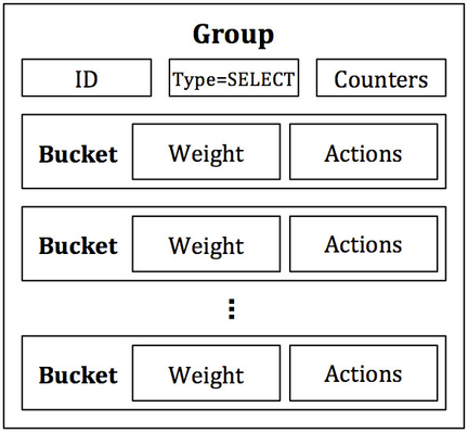
Figure 3: The SELECT group. A single packet is dispatched to a single bucket, selected from the list of buckets. The packet distribution/bucket selection algorithm is undefined but can utilize the weight parameter specified in each bucket.
The INDIRECT Group
The INDIRECT group (Figure 4) can be difficult to comprehend as a “group,” since it contains only a single bucket where all packets received by the group are sent to this lone bucket. In other words, the INDIRECT group does not contain a list of buckets but a single bucket (or single list of actions) instead. The purpose of the INDIRECT group is to encapsulate a common set of actions used by many flows. For example, if flows A, B, and C match on different packet headers but have a common set or subset of actions, these flows can send packets to the single INDIRECT group as opposed to having to duplicate the list of common actions for each flow. The INDIRECT group is used to simplify an OpenFlow deployment and reduce the memory footprint of a set of similar flows.
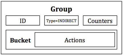
Figure 4: The INDIRECT group. All packets are dispatched to a single bucket with no special parameters. The purpose of an INDIRECT group is to consolidate common actions of a set of flows in order to reduce flow table memory consumption.
The FAST-FAILOVER Group
Lastly, the FAST-FAILOVER group is the topic of conversation for this tutorial and is designed specifically to detect and overcome port failures. Like the SELECT and ALL groups, the FAST-FAILOVER group, as indicated in Figure 5, has a list of buckets. In addition to this list of actions, each bucket has a watch port and/or watch group as a special parameter. The watch port/group will monitor the “liveness” or up/down status of the indicated port/group. If the liveness is deemed to be down, then the bucket will not be used. If the liveness is determined to be up, then the bucket can be used. Only one bucket can be used at a time, and the bucket in use will not be changed unless the liveness of the currently used bucket’s watch port/group transitions from up to down. When such an event occurs, the FAST-FAILOVER group will quickly select the next bucket in the bucket list with a watch port/group that is up.
There is no guarantee on the transition time to select a new bucket when a failure occurs. The transition time is dependent on search time to find a watch port/group that is up and on the switch implementation. However, the motivation behind using a FAST-FAILOVER group is that it is almost guaranteed to be quicker than consulting the control plane to handle the port down event and inserting a new flow or set of flows. With FAST-FAILOVER groups, link failure detection and recovery takes place entirely in the data plane.
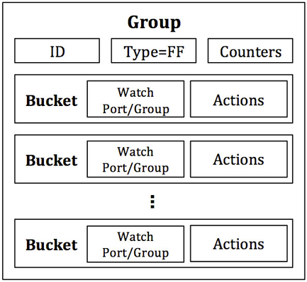
Figure 5: The FAST-FAILOVER (FF) group. A FF group is designed to detect and respond to port failures. Each bucket has a watch port/group as a special parameter, which monitors the liveness of that port or group being watched. Only one bucket is used at a time, and the bucket will only be changed if the watch port/group of the bucket transitions from up to down. Upon such an event, another bucket will be chosen whose watch port/group indicates the link is up.
Experiment Design
We use a FAST-FAILOVER group in this tutorial as a vehicle to demonstrate the potential of features present in OpenFlow 1.3. A simple, basic topology is used to decrease extraneous tasks and cognitive load. As such, we can to focus on the core of what is necessary to work with a FAST-FAILOVER group. The Floodlight OpenFlow controller is used to demonstrate the use of a FAST-FAILOVER group from the perspective of the control plane and to help bring links up and down for demonstration.
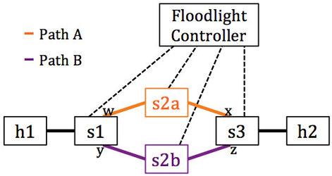
Figure 6: Experiment topology. We will use FAST-FAILOVER groups on s1 and s3 to automatically switch between paths A and B upon a link failure. The ports that will participate in the groups are indicated by ports w, x, y, and z.
Figure 6 above shows the topology we will use. There are four OpenFlow switches – s1, s2a, s2b, and s3 – and two hosts – h1 and h2. The switches are arranged in a ring topology with one host attached at each side of the ring. The objective is to use FAST-FAILOVER groups on s1 and s3 to automatically switch between path A and path B in the event of a port (and thus link) failure on either of the paths.
To accomplish this task, each switch is configured with the Floodlight controller as its controller. Floodlight is equipped with a special module just for this experiment that is responsible for inserting the flows and FAST-FAILOVER groups that facilitate the reliable communication between h1 and h2 across paths A and B. For simplicity, the topology is assumed to be the ring depicted in Figure 6.
When all switches are connected, the controller will use LLDP to discover and verify the links in between each switch and to learn the switch port numbers at each end of a particular link. After the links have been detected, to trigger the insertion of flows and groups, a REST API is used in our custom Floodlight module. The first time the REST API is invoked, the groups and flows are inserted on each applicable switch.
Each subsequent call to our module's same REST API will cause the controller to issue port configuration messages to the switches to administratively bring up and take down ports along either path A or path B. The ports that will be brought up and down via port configuration messages are indicated by ports w, x, y, and z in Figure 6. This simulates the two links going up and down and shows how the FAST-FAILOVER groups on s1 and s3 automatically switch to the alternative path.
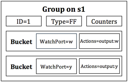
Figure 7: The FAST-FAILOVER group on s1. Note the correlation between the watch port and output port within each bucket.
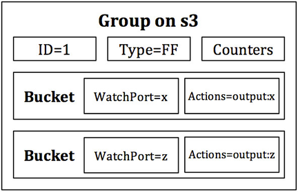
Figure 8: The FAST-FAILOVER group on s3. Note the correlation between the watch port and output port within each bucket.
The groups present on s1 and s3 are FAST-FAILOVER groups with watch ports set to the ports of each link connecting to the opposite side of the network. Figures 7 and 8 are graphical representations of the groups that will be installed in s1 and s3, respectively. When a port of the set w, x, y, and z is administratively brought up and another taken down, the group will change to the bucket watching the live port, and the transmission of data will not be disrupted between h1 and h2. Note that the actions of each bucket in Figures 7 and 8 output to the port that is being watched. If a bucket is chosen, then the watch port must be up, thus the output action will be executed on a connected link.
Resource Allocation
You should create your topology either in a GENI slice using the provided rspec or using some other method with your own resources. If you would like to link to the GENI rspec URL using a tool like Jacks, you can do so using this link.
Note that Open vSwitch (OVS) 2.3.1 or above is required, as prior versions of OVS only seem to have protocol support for FAST-FAILOVER groups and not an actual software implementation. (OVS 2.2.0 does not support FAST-FAILOVER groups but 2.3.0 has not been tested and might have support.)
There are three types of devices used in the topology: hosts, OVSs, and the controller. Hosts are used to send and receive data on the data plane network. OVSs are given as s1, s2a, s2b, and s3 and are designed to relay traffic to and from the h1 and h2 hosts according to the topology shown in Figure 6. And, of course, the controller is where the Floodlight OpenFlow controller lives.
If you would like to use mininet, a mininet custom topology script is provided here. Please skip to Controller Configuration below if using mininet. Your mininet topology should handle all OVS links/interconnects and hosts.
OVS Configuration
If using GENI, once you are able to login to your resources, you will need to configure each OVS machine with an OVS instance. Fortunately, the images used in the rspec already have a OVS 2.3.1 installed. The following steps should be taken on each OVS. OVS machine s1, is used as an example.
1) Create an OVS bridge.
s1$ sudo ovs-vsctl add-br br_ovs
2) Determine which interfaces in each OVS machine correspond to the purple and orange data plane links in Figure 6. You can match subnets between interfaces of adjacent machines, since each link should have a unique subnet. All control plane interfaces should be on the same subnet, since they are on the same LAN.
3) Add these data plane network interfaces that correspond to the data plane links to the created OVS bridge as ports.
s1$ sudo ovs-vsctl add-port br_ovs <ethX-facing-h1>
s1$ sudo ovs-vsctl add-port br_ovs <ethY-facing-s2a>
s1$ sudo ovs-vsctl add-port br_ovs <ethZ-facing-s2b>
4) Set the Datapath ID (DPID) of each switch according to the following convention:
| OVS Bridge | DPID |
|---|---|
| s1 | 00:00:00:00:00:00:00:01 |
| s2a | 00:00:00:00:00:00:00:2a |
| s2b | 00:00:00:00:00:00:00:2b |
| s3 | 00:00:00:00:00:00:00:03 |
Note that you can use different DPIDs if you wish; however, the controller will expect these, and modification to these DPIDs will require modification to our custom Floodlight module.
s1$ sudo ovs-vsctl set bridge br_ovs other-config:datapath-id=0000000000000001
5) Set the controller of each switch to the private IP of the controller VM. For example, if your control LAN interface on s1 is ethX with IP 10.10.9.1/24, and on the controller machine you have an ethY with IP 10.10.9.2/24, then you would set s1's controller IP to 10.10.9.2.
s1$ sudo ovs-vsctl set-controller br_ovs tcp:<controller-ip-here>:6653
6) Bring down the IP addresses of each network interface used as a data plane link. This, although not absolutely necessary, will prevent any packets from leaking from the data plane. Be careful and do not inadvertently take down your control interface or control plane link.
s1$ sudo ifconfig <ethX-facing-h1> 0.0.0.0
s1$ sudo ifconfig <ethY-facing-s2a> 0.0.0.0
s1$ sudo ifconfig <ethZ-facing-s2b> 0.0.0.0
7) Set the fail mode of each OVS bridge to secure.
s1$ sudo ovs-vsctl set-fail-mode br_ovs secure
Host Configuration
Configure the data plane networks interfaces of h1 and h2 with IPs on the same subnet.
h1$ sudo ifconfig <ethX-facing-s1> 10.0.0.1/24
h2$ sudo ifconfig <ethY-facing-s3> 10.0.0.2/24
Controller Configuration
1) Update repositories and install git, ant, curl, and Java 7. Note: We require Java 7 in order to run Floodlight. If you are using an older version of Linux (such as Ubuntu 12), you might need to manually install Java 7 if your default is not that already. Ubuntu 14’s default is Java 7, so the instructions below should work directly for Ubuntu 14.
controller$ sudo apt-get update
controller$ sudo apt-get install git ant curl default-jre default-jdk
2) Download the Floodlight controller source code. Note that you should use this repository and not the main Floodlight repository.
controller$ git clone -b tutorial git://github.com/rizard/fast-failover-demo
3) Setup the controller.
controller$ sudo mkdir /var/lib/floodlight
controller$ sudo chmod 333 /var/lib/floodlight
controller$ cd directory-where-you-cloned-floodlight/fast-failover-demo
controller$ ant
controller$ java -jar target/floodlight.jar
Verify Control Plane Connections
All switches should now report a connection to the controller, for example:
s1$ sudo ovs-vsctl show
    89362c3a-1d64-451b-977d-7b2718a1ba20
    Bridge br_ovs
    Controller "tcp:10.10.7.1:6653"
       is_connected: true
       fail_mode: secure
    Port "eth1"
       Interface "eth1"
    Port "eth3"
       Interface "eth3"
    Port br_ovs
       Interface br_ovs
           type: internal
    Port "eth4"
       Interface "eth4"
    ovs_version: "2.3.1"
And the controller log should indicate the same. To check each switch’s connection to the controller, Floodlight’s REST API can also be used. While the controller is running, either in a different SSH session to the controller machine or by using a utility like screen, run the following:
controller$ curl http://localhost:8080/wm/core/controller/switches/json | python -m json.tool
            …
            [
    			{
        			"connectedSince": 1431639757137,
        			"inetAddress": "/10.10.9.2:41320",
        			"switchDPID": "00:00:00:00:00:00:00:2b"
    			},
    			{
        			"connectedSince": 1431639757176,
        			"inetAddress": "/10.10.8.1:40399",
        			"switchDPID": "00:00:00:00:00:00:00:2a"
    			},
    			{
        			"connectedSince": 1431639757175,
        			"inetAddress": "/10.10.7.2:39946",
        			"switchDPID": "00:00:00:00:00:00:00:01"
    			},
    			{
        			"connectedSince": 1431639757136,
        			"inetAddress": "/10.10.10.2:38549",
        			"switchDPID": "00:00:00:00:00:00:00:03"
    			}
			]
If all switches report connected, then the control plane is configured correctly. Please shutdown Floodlight by killing the controller Java process or by issuing a SIG_INT (CTL+c). We will need to extend our custom Floodlight module in order to conduct the experiment.
On the controller, Floodlight will by default run in the foreground and the log will clutter stdout. We will need to run curl to access the controller REST API. We can run it from any OVS VM; however, in this tutorial, we will run it from the controller VM to keep all control plane operations in a single place. You can choose to do what you are most comfortable with. If you choose to run curl from the controller VM, the program screen is recommended to run the Floodlight process in an accessible way and “out of the way.” Two other possibilities are to (1) run Floodlight in the background and redirect its output to someplace else or to (2) establish a second SSH session to the controller VM leaving the controller process running in the first SSH session. The remaining instructions are given in an agnostic way with regard to how you choose to interact with the processes on the controller VM.
Get Your Hands Dirty and Write Some Floodlight Code
Not Recommended: Skip Writing Floodlight Code and Use Solution
I'll mention up front that if you aren't interested in learning how to compose group messages, do not need to learn the Floodlight code, or you would like to "cheat" and/or get some help arriving at the solution, you can clone or take a look at the solution branch:
http://github.com/rizard/fast-failover-demo/tree/solution
Or to change to the solution branch (within your cloned repository):
controller$ git checkout -b solution origin/solution
If you would like to start with the solution branch, you can skip to skip to Run Experiment.
Recommended: Learn How to Write the Floodlight Code
However, if you are up for a challenge, you will be walked through writing the missing pieces of the controller module – specifically, writing an ofp_group_mod message to create the FAST-FAILOVER group for s1 and a couple ofp_flow_mod messages to direct packets into the created group in s1. The process for s3 is almost identical and has been implemented for you; we will not implement it since it's somewhat redundant.
All other parts of the demonstration module simply automate the learning of switch ports, handle switch connections to the controller, and implement the REST API used to trigger "port/link failure" events for the purpose of the tutorial. In the real world, such failures are not typically triggered and are circumstantial.
A Brief Introduction to the Components of the Demonstration Code
The Fast-Failover-Demo version of Floodlight is based on Floodlight v1.1 and is extended with a module called FastFailoverDemo within the net.floodlightcontroller.fastfailoverdemo package. This package can be found within your cloned repository at src/main/java/net/floodlightcontroller/fastfailoverdemo. (Notice a pattern?) Our module is responsible for inserting the flows and groups necessary to implement a basic FAST-FAILOVER group deployment. The Forwarding module (a learning switch implementation) is disabled to allow us to have complete control over the topology such that only our module will insert flows.
Within src/main/java/net/floodlightcontroller/fastfailoverdemo, there is a FastFailoverDemo.java file – this is where the majority of the logic is located and is the Floodlight module itself. Within this file is where we will fill in the missing pieces to complete the tutorial. It contains the flow and group modification messages that are sent to the switches s1, s2a, s2b, and s3 in our topology in Figure 6. This file also contains logic to allow for automatic switch port discovery and learning for use in our flows and groups. In other words, it allows us to hard-code less data and provide a more realistic real-world module. In tandem with the switch port learning is switch detection and monitoring. These are accomplished by querying the link discovery service for links and for registering with the switch manager as a listener for switch events. Lastly, a handler for the REST API is included to receive commands to emulate port up/down events to cause the installed groups to change to path A or path B, as shown in Figure 6.
Also in src/main/java/net/floodlightcontroller/fastfailoverdemo is IFastFailoverDemoService.java. This is an interface that exposes our module as a service to other Floodlight modules, such as the REST API module. As such, when a REST command is received, our module's handler can be invoked as a service by the REST API module. Only services and listeners are visible to other modules from outside one's own module.
Next, in src/main/java/net/floodlightcontroller/fastfailoverdemo/web is FastFailoverDemoRoutable.java. This is what plugs into the REST API module and registers our URI /wm/fast-failover-demo/toggle-path. This leads us to src/main/java/net/floodlightcontroller/fastfailoverdemo/web/TogglePathResource.java, which is the REST API module's registered handler for a call to /wm/fast-failover-demo/toggle-path; the registration of this handler is shown in FastFailoverDemoRoutable.java. As shown in TogglePathResource.java, the service exposed by our module is retrieved and our module's handler in src/main/java/net/floodlightcontroller/fastfailoverdemo/FastFailoverDemo.java is invoked.
You will also notice src/main/java/net/floodlightcontroller/fastfailoverdemo/web/ResetResource.java, which handles /wm/fast-failover-demo/reset commands to the REST API. This will allow you to reset all switch ports and bring them up at any point in time. At this point, we have come full-circle and can now get to writing some code!
Writing an ofp_group_mod in Floodlight
In Floodlight, an ofp_group_mod with ofp_group_mod_command=OFPGC_ADD (i.e. to add a group) is exposed as an OFGroupAdd. We will create and send this OFGroupAdd message in the insertFlows() function at line 631 in src/main/java/net/floodlightcontroller/fastfailoverdemo/FastFailoverDemo.java.
As discussed above, a group has a list of buckets. We want to have two buckets representing each path from s1 to s3 in our topology. Each bucket will output to the switch port number of that link. These port numbers are contained in Link variables link_dpid1_to_dpid2a and link_dpid1_to_dpid2b. The variables names should be self-explanatory, but what you need to know is that a Link is a class containing the source switch, source port, destination switch, and destination port of the link. The following functions are exposed publicly by Link to get the ports:
OFPort theSrcPort = someLink.getSrcPort(); // get source port of link
OFPort theDstPort = someLink.getDstPort(); // get destination port of link
An an example, for link_dpid1_to_dpid2a, the source is s1 and destination is s2a, thus the switch port leaving s1 on this link (path A in Figure 6) can be attained by asking the Link for its source port. Likewise, the switch port of link_dpid1_to_dpid2a entering s2a can be attained by asking the Link for its destination port. We will use these switch ports to automatically determine the switch ports we need rather than hard coding them.
Let's first compose the two buckets required for our FAST-FAILOVER group. Recall that a bucket contains a list of actions an an optional special parameter depending on the group type. A FAST-FAILOVER group has a watch port and watch group as special parameters, which ascertain the liveness of the watched port or group. This liveness will determine whether or not the bucket is chosen and thus which path – path A or path B – is chosen. We want to watch the liveness of the ports leading to paths A and B. If either of these ports go down, we do not want to use the path. As such, the watch port is the same as the port we will use as an output action in the bucket's actions.
ArrayList<OFBucket> buckets = new ArrayList<OFBucket>(2);
buckets.add(sw1.getOFFactory().buildBucket()
	.setWatchPort(link_dpid1_to_dpid2a.getSrcPort())
	.setWatchGroup(OFGroup.ZERO)
	.setActions(Collections.singletonList((OFAction) sw1.getOFFactory().actions().buildOutput()
		.setMaxLen(0xffFFffFF)
		.setPort(link_dpid1_to_dpid2a.getSrcPort())
		.build()))
	.build());
buckets.add(sw1.getOFFactory().buildBucket()
	.setWatchPort(link_dpid1_to_dpid2b.getSrcPort())
	.setWatchGroup(OFGroup.ZERO)
	.setActions(Collections.singletonList((OFAction) sw1.getOFFactory().actions().buildOutput()
		.setMaxLen(0xffFFffFF)
		.setPort(link_dpid1_to_dpid2b.getSrcPort())
		.build()))
	.build());
The next step is to create our group. Our group is a FAST-FAILOVER group and will use the bucket list we just created above. This process also involves assigning a group ID.
OFGroupAdd groupAdd = sw1.getOFFactory().buildGroupAdd()
	.setGroup(OFGroup.of(1))
	.setGroupType(OFGroupType.FF)
	.setBuckets(buckets)
	.build();

sw1.write(groupAdd);
Write the ofp_flow_mods in Floodlight
We next need to compose the ofp_flow_mods to send packets from h1 into our group. These flows will be placed immediately after the ofp_group_mod code we wrote above (specifically, we want to place the flows here). We want to permit all ARP and IPv4 packets, so we will have two separate flows to accomplish this task. New flows can be constructed in Floodlight through an OFFlowAdd. In our topology (Figure 6), s1 and s3 have two links with ports, the LOCAL port, and another port leading to the the hosts, h1 and h2, respectively. By process of elimination, we can determine the switch port of s1 where h1 is attached. This is done in the getHostPort(IOFSwitch mySwitch) function, which takes an IOFSwitch as an argument and returns an OFPort. For s1, IOFSwitch s1 will be the argument and the port leading to h1 will be returned as the ingress port for our flows. (Note that the device manager in Floodlight could also be used to accomplish this, but an "in house" method is more transparent and also does not depend on the generation of traffic by the hosts in order for them to be added as devices in Floodlight.) The following is the construction of the ARP flow:
OFFlowAdd flowAdd = sw1.getOFFactory().buildFlowAdd()
	.setCookie(cookie)
	.setHardTimeout(0)
	.setIdleTimeout(0)
	.setPriority(FlowModUtils.PRIORITY_MAX)
	.setMatch(sw1.getOFFactory().buildMatch()
		.setExact(MatchField.ETH_TYPE, EthType.ARP)
		.setExact(MatchField.IN_PORT, getHostPort(sw1))
		.build())
	.setActions(Collections.singletonList((OFAction) sw1.getOFFactory().actions().buildGroup()
		.setGroup(OFGroup.of(1))
		.build()))
	.build();

sw1.write(flowAdd);
Note that our action is to send the packets to our group created and installed previously. We must have installed the group in the switch before we are allowed to reference the group in any flows.
Next, we can construct a similar flow for IPv4 packets. Because only the Match changes, we can use our ARP OFFlowAdd flowAdd as a starting point and simply change the Match:
flowAdd = flowAdd.createBuilder()
	.setMatch(sw1.getOFFactory().buildMatch()
		.setExact(MatchField.ETH_TYPE, EthType.IPv4)
		.setExact(MatchField.IN_PORT, getHostPort(sw1))
		.build())
	.build();

sw1.write(flowAdd);
Lastly, you will notice a block of code in the controller immediately below where you just composed your OFFlowAdds. It looks like this:
/*
 * START REMOVE ME
 *
 * FIXME Remove this block of code after you have implemented the tutorial.
 * It is only here to allow the controller to compile with the missing code.
 */
OFFlowAdd flowAdd = null;
if (flowAdd == null) {
	throw new IllegalStateException("Need to implement tutorial first. If you've implemented the necessary code here, perhaps you need to remove this message?");
}
/*
 * END REMOVE ME
 */
Please remove this block of code. Its only purpose was to allow the controller to compile without the code you just wrote. If you forget to remove this code, your module will not work properly and you will likely get a compile error for redeclaration of a variable.
Run Experiment
We need to compile our changes to the Floodlight controller and start it. On the controller:
controller$ cd directory-where-you-cloned-floodlight/fast-failover-demo
controller$ ant clean
controller$ ant
controller$ java -jar target/floodlight.jar
Next, we need to setup a way to monitor the two paths in the topology in order to observe the path being used. To do this, we will login to the s2a and s2b OVSs and run tcpdump to monitor network activity.
s2a$ sudo tcpdump -i ethX -n arp or icmp
s2b$ sudo tcpdump -i ethY -n arp or icmp
Note that ethX and ethY are any interface on s2a and s2b, respectively, that are data plane network interfaces.
Lastly, let’s start a ping from one host to the other. We set h1's IP to 10.0.0.1/24 and h2's IP to 10.0.0.2/24; thus, if we want to ping from h1 to h2, we can ping 10.0.0.2 from h1.
h1$ ping 10.0.0.2
At this point, there are no flows in the network and learning switch is disabled in the controller, so the ping should fail. We need to issue an initial command to the REST API of our Floodlight module to trigger it to create and insert the flows and groups.
controller$ curl http://localhost:8080/wm/fast-failover-demo/toggle-path -X POST -d '' | python -m json.tool
            …
            {
            	"STATUS", "SUCCESS",
				"DETAILS", "Inserted groups and flows. Administratively set ports along path A up and path B down. You should observe path A being chosen by the FAST-FAILOVER groups, which can be verified by observing packets on s2a on path A"
            }
For simplicity, there is a single API exposed for our module: toggle-path. For safety reasons, it accepts either a POST or a PUT but not a GET. Thus, we send an empty string using -d ‘’ in our request.
Aside: You should seldom if ever create a REST API that allows a HTTP GET to perform modifications to the application, aside from perhaps debug or event counters. A HTTP GET can be sent inadvertently or maliciously through something as simple as an email containing the URL to your REST API that will be fetched when the email is opened. (Email is just an example here.)
After the flows and groups are inserted, an initial path is chosen after sending the port modification messages to s1 and s3. We can observe the path being used in the tcpdump output on s2a and s2b. One path should see packets, and the other path should show nothing.
Next, we can call the REST API of our Floodlight module once again.
controller$ curl http://localhost:8080/wm/fast-failover-demo/toggle-path -X POST -d '' | python -m json.tool
           …
           {
           		"STATUS", "SUCCESS",
				"DETAILS", "Administratively set ports along path B up and path A down. You should observe path B being chosen by the FAST-FAILOVER groups, which can be verified by observing packets on s2b on path B"
           }
The path being used will toggle, and we will observe that the tcpdump output on the previously down link now shows our packets as they traverse the link. At the same time, the previously up link will not show any additional packets traversing the link.
We can repeat this process to simulate alternating link failures and show how the fast-failover groups installed on s1 and s3 automatically change to the link that is up. The control plane is only used to insert the flows and groups initially. A link failure is handled entirely within the data plane once the groups have been inserted.
Note, if for any reason you need to reset all ports to up/enabled, you can call the reset API as follows. Do not do this unless you feel you have made a mistake and/or your groups are not working.
controller$ curl http://localhost:8080/wm/fast-failover-demo/reset -X POST -d ''
Verify Results
Now that we have shown how the groups work, let’s take a look at what they look like installed on our switches. The results given below are only examples. Your port numbers, counters, and port statuses might vary, but the general observation is the same. Note: If using mininet, substitute "br_ovs" with your bridge name.
The groups are on s1 and s3. So, on the s1 and s3 OVSs, issue the following:
s1$ sudo ovs-ofctl dump-flows br_ovs -O OpenFlow13 table=0
	…
    cookie=0x11223344, duration=487486.386s, table=0, n_packets=0,n_bytes=0, arp,in_port=2 actions=output:4
    cookie=0x11223344, duration=487486.384s, table=0, n_packets=184,n_bytes=18032, ip,in_port=3 actions=output:4
    cookie=0x11223344, duration=487486.385s, table=0, n_packets=0,n_bytes=0, arp,in_port=3 actions=output:4
    cookie=0x11223344, duration=487486.385s, table=0, n_packets=1229,n_bytes=120442, ip,in_port=2 actions=output:4
    cookie=0x11223344, duration=487486.387s, table=0, n_packets=0,n_bytes=0, arp,in_port=4 actions=group:1
    cookie=0x11223344, duration=487486.386s, table=0, n_packets=1413, n_bytes=138474, ip,in_port=4 actions=group:1
Examining the output above, we can see in our default flow table the flows we inserted to direct all IPv4 and ARP packets to group 1. Now, let’s see what group 1 contains. Also on the s1 and s3 OVSs, issue the following:
s1$ sudo ovs-ofctl dump-groups br_ovs -O OpenFlow13
    …
    group_id=1,type=ff,
		bucket=weight:0,watch_port:2,watch_group:0,actions=output:2,
        bucket=weight:0,watch_port:3,watch_group:0,actions=output:3
We only have a single group in the group table, and it is type “ff” or FAST-FAILOVER. As shown, there are two buckets – one corresponding to each link in our topology. Each bucket watches the port to which it outputs. If the port being watched by the bucket is down, the bucket will not be used. However, if the port being watched by the bucket is up, it is a candidate for use.
The ports given in the group buckets were determined automatically via Floodlight’s link discovery manager. We can verify the ports exist and correspond to network interfaces of our data plane by issuing the following on both s1 and s3 OVSs:
 s1$ sudo ovs-ofctl show br_ovs
    OFPT_FEATURES_REPLY (xid=0x2): dpid:0000000000000001
    …
	2(eth1): addr:02:2f:1e:94:84:3b
     	config:     PORT_DOWN
     	state:      LINK_DOWN
     	speed: 0 Mbps now, 0 Mbps max
 	3(eth4): addr:02:90:e2:e8:f3:39
     	config:     0
     	state:      0
     	speed: 0 Mbps now, 0 Mbps max
 	4(eth3): addr:02:b6:89:af:bd:79
     	config:     0
     	state:      0
     	speed: 0 Mbps now, 0 Mbps max
 	LOCAL(br_ovs): addr:f2:83:05:f1:3e:48
     	config:     PORT_DOWN
     	state:      LINK_DOWN
     	speed: 0 Mbps now, 0 Mbps max
	OFPT_GET_CONFIG_REPLY (xid=0x4): frags=normal miss_send_len=0
Also observed in the output above is the port that we administratively set down, port 2 or eth1. Port 2 is being watched by the first bucket in group 1’s bucket list. Because port 2 is down, the first bucket will not be used by the FAST-FAILOVER group. Notice that the second bucket watches port 3, which is up according to the output above. As a result, the second bucket can be used in the FAST-FAILOVER group. In fact, since it’s the only bucket that is up, the second bucket must be used by the group.
What Next?
If you are interested in or need help with other OpenFlow 1.3 topics that do not have a tutorial, write to our email list. Please also use the mailing list if you have questions or have trouble with this OpenFlow groups tutorial.