Indigo - OpenFlow for Hardware Switches
Goals
After reading through this web page, you should be able to revive a 3290 by booting from the backup boot image and reloading the normal boot images. This procedure should also work on the Pronto 3780.
This document does not apply to the LB4G/Pronto 3240.
The Problem
The 3290 normally loads its boot image from the compact flash card. If this image has a problem and cannot boot, you need to load the back up image and copy a new image back to the compact flash. This requires using the serial port.
If you are able to boot to the u-boot prompt but are not able to load the flash image (with 'run flash_bootcmd') then you may be able to reload the flash files to the switch. See Reflashing a Pronto Switch.
Prerequisites
You will need the following for this procedure.
- The Pronto switch
- A computer with software that can communicate via a serial port.
- A serial port cable to connect the switch and computer. See Serial Ports on Quanta and Pronto for more information.
- A computer (could be the same one as above) running a TFTP server (see the Appendix on the page Up and Running on the 3290)
- A cable to connect the Pronto switch and the TFTP server. (Or connect them to a switch or network. They must be on the same subnet.)
- The Indigo binary images you want to load on the switch. These must be placed in the TFTP server's TFTP directory (usually /tftpboot or /var/tftpboot).
- An IP address for the switch on the same subnet as your TFTP server.
- The configuration information of the switch in case the configuration has been corrupted or lost. This usually includes
- The IP address of the switch
- The IP address and TCP port number you will use to connect to the controller
- The IP address of a router if the controller is not on the same subnet as the switch
- The dathpath ID to be assigned to the switch
- A name for the switch (optional)
Connect and Boot
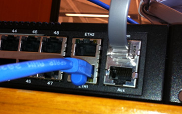
Once you've connected the serial port to the switch as shown on the page Serial Ports on Quanta and Pronto, connect the Ethernet port labeled ETH1 on the front panel of the switch to your TFTP server or network.
|
This shows the connection of the Ethernet and serial ports |
Connect to the serial port. In the screenshots below, I'm connected to a serial port server by telnet, but the content of the screens should look the same.
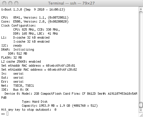
Power on the switch and wait a few seconds for the banner announcing u-boot to show up. It should give you a count down timer. Hit the space key within 5 seconds and you should get to the => prompt indicating you are talking to u-boot, the boot loader.
In order to boot from flash, you need to give the right command. By default, this is the command flash_bootcmd. Verify this is defined by typing 'printenv' at the prompt.
=> printenv
...
flash_bootcmd=setenv bootargs root=/dev/ram console=ttyS0,$baudrate; bootm ffd00000 ff000000 ffee0000
...
If you do not see this variable, you can set it yourself. You must be very careful about using proper quoting and putting the entire command on one line. To get the variable defined as above, you would type:
setenv flash_bootcmd 'setenv bootargs root=/dev/ram console=ttyS0,$baudrate; bootm ffd00000 ff000000 ffee0000'
saveenv
Pay special attention to the placement of the single quotes ' ' and do not extend this across more than one line. (It's okay if the command is longer than one line, but don't hit the return key or use the \ key in the middle of the line.) After entering changes, make sure you type 'saveenv' to save your changes.
Now type
run flash_bootcmd
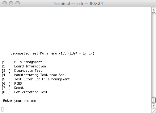
The system should indicate it is loading the Linux kernel and then the root file system. After a few more seconds, you will see a lot of output as the system comes up. Eventually, you should see a menu like the following:
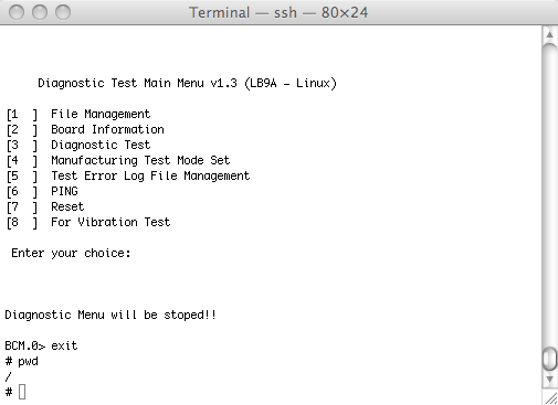
Exit this menu by typing Control-D. You should see the prompt BCM.0>. Type 'exit' here. You should see #, the Linux shell prompt.
Configuring the Network
You now need to configure the network interface of the switch to be on the same subnet as the TFTP server.
NOTE: This is a little confusing. The port labeled ETH1 on the front panel is referred to as eth0 from the Linux shell.
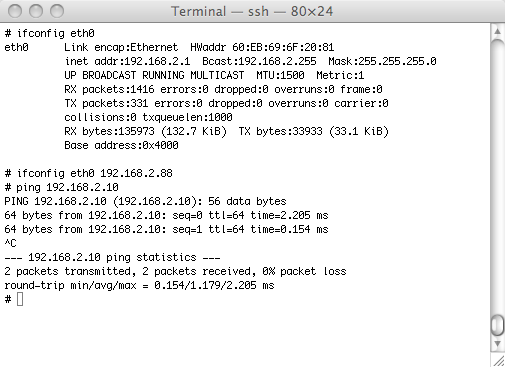
By default eth0 will probably be configured with the address 192.168.2.1. This may work for your setup if the TFTP server is on that network. In the window below, we show the current configuration, reconfigure to the address 192.168.2.88 and ping the TFTP server which has the address 192.168.2.10.
Load the images
Having verified that we can connect to the TFTP server, we can now load the new images.
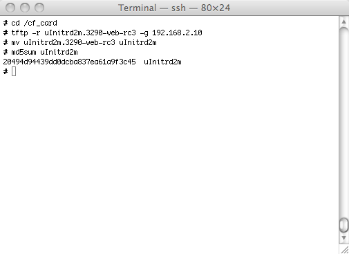
Change directory to /cf_card
cd /cf_card
You probably only need to copy the root file system from the TFTP server. The following command assumes that the file you want to load is called uInitrd2m and that the TFTP server is 192.168.2.10.
tftp -r uInitrd2m -g 192.168.1.10
The Busybox TFTP client is quite picky about the order of flags in the command above. If you change the order, it may not work.
It is highly recommended that you verify that the md5sum matches what you expect. This should be in a file called md5sums that came with the image.
md5sum uInitrd2m
The screen shot below shows this where the image we copy has a different name. So we move it to uInitrd2m. The file must be uInitrd2m to be booted (unless you change the boot command in u-boot).
The other files you may need to load are the Linux kernel, uImage, and the device description file, LB9A.dtb. Repeat the 'tftp -r' and md5sum commands for these files if required.
Configure and Reboot
If you are not sure if the current configuration is a problem, you can clear out the current one and place a minimal sysenv file in its place. The configuration is stored in the file /cf_card/local/sysenv. Older versions of the configuration are in /cf_card/local/cfg_history.
To replace the configuration, try:
cd /cf_card/local
ls sysenv
# If sysenv is there:
mv sysenv sysenv.old
echo "export switch_ip=192.168.2.88" > sysenv
This assumes that you want to configure the system with the IP address 192.168.2.88. If it exists, you can save the existing sysenv file, in this case to a file named sysenv.old.
You can now reboot your system by typing "reboot". Without intervention, the system should come up and run the firmware you just loaded. You can now either use the CLI or the web interface to complete the process of configuring the switch. To do this using the CLI, see the section Setting the System Configuration on the page Reflashing a Pronto Switch.
Add Comment